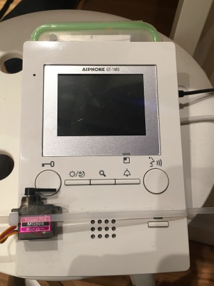
Doorbot is an Internet-connected door unlocker that I built for a community space. It allows people to enter the space without needing to be buzzed in.
System Architecture
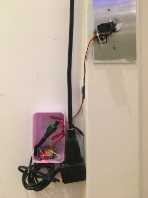
The Doorbot system consists of:
servo motors to actuate the door buzzer button
ESP8266 microcontroller with built-in Wi-Fi
NodeMCU firmware for ESP8266
lua application code for ESP8266
MQTT message broker
web app with user authentication
The web app sends HMAC-signed command messages to the MQTT broker. The microcontroller waits for command messages to actuate the servo motor and unlock the door.
The microcontroller also sends periodic heartbeat messages so that the web app can show when Doorbot is offline.
This post is a short overview of what is required for a minimal, download-only BitTorrent implementation.
Earlier this year, I wrote a BitTorrent client as an excuse to practice concurrency and networking concepts. But the resources and documentation I found while researching the protocol felt scattered, so I’m distilling my understanding here as a starting point for others.
1. Parse the .torrent metainfo file
The .torrent file contains information about the torrent tracker and the files to be downloaded.
Data is encoded using a serialization protocol called bencoding.
Parsing bencoded data is not significantly more difficult than parsing json, and there is likely a bencoding library available for your language.
2. Connect to the tracker
To connect to the torrent, an HTTP GET request is made to the tracker announce URL.
The response provides a list of available peers.
3. Concurrent peer network connections
The client will connect to peers using TCP sockets.
To support multiple simultaneous connections the client should be able to handle network operations asynchronously.
There are two fundamental ways to do this in Python: (1) using threads, or
(2) using an event loop with select() (or a library like Twisted which does so internally).
4. Peer protocol
The spec defines a number of messages that each peer must be prepared to send and receive.
A minimal BitTorrent client may not need to implement all of these messages.
In order to start downloading from a peer, a client needs to send a handshake, wait for a handshake response,
send an ‘interested’ message, and wait for an ‘unchoke’ message.
It can then start sending ‘request’ messages to request blocks.
The peer will respond with ‘piece’ messages which contain the block data.
5. Torrent strategy
The client must download all blocks of all pieces and assemble them into the complete output file
set. If any peers disconnect or fail to provide a block, the client must request from another peer.
A more ambitious client may also attempt to further optimize its download strategy to improve download times.
Further reading
I found the following blog posts to be very helpful when I was getting started:
The best advice I picked up from them is (1) to rely on the unofficial BitTorrent spec, and (2) to use Wireshark to inspect network traffic to clarify ambiguities in the spec and to validate your implementation.
There are now many extensions to the original BitTorrent protocol, so you should stick with .torrent files that do not use new or experimental features for your testing. I have had good luck with torrents from archive.org and bt.etree.org.
A conversation with a coworker turned me on to the fact that a surprising range of operations in Python are atomic, even operations like dictionary and class member assignment.
This wasn’t something I would have anticipated, given the number of machine language instructions that must ultimately be performed to complete an operation like hash table insertion.
Why?
The Python FAQ provides explanation and a full list of atomic operations, but the short answer is:
The Python bytecode interpreter only switches between threads between bytecode instructions
The Global Interpreter Lock (GIL) only allows a single thread to execute at a time
Many operations translate to a single bytecode instruction
It’s easy to check whether an operation compiles to a single bytecode instruction with dis.
So what are the caveats? Is it safe to rely on atomicity instead of using locks?
First, the linked FAQ above doesn’t make it clear to what degree this behavior is considered part of the Python spec as opposed to simply a consequence of CPython implementation details.
It depends on the GIL, so it would likely be unsafe on GIL-less Pythons (IronPython, Jython, PyPy-TM).
Would it be safe on non-CPython implementations with a GIL (PyPy)?
I could certainly imagine possible optimizations that would invalidate the atomicity of these operations.
Second, even if not strictly necessary, locks provide clear thread-safety guarantees and also serve as useful documentation that the code is accessing shared memory.
Without a lock, care must be taken since it could be easy to assume operations are atomic when they are not (postmortem example: Python’s swap is not atomic).
A clear comment is probably also necessary to head off the “Wait, this might need a lock!” reaction from collaborators.
Third, because Python allows overriding of so many builtin methods, there are edge cases where these operations are no longer atomic. The Google Python style guide advises:
Do not rely on the atomicity of built-in types.
While Python’s built-in data types such as dictionaries appear to have atomic operations, there are corner cases where they aren’t atomic (e.g. if hash or eq are implemented as Python methods) and their atomicity should not be relied upon. Neither should you rely on atomic variable assignment (since this in turn depends on dictionaries).
That pretty much settles it for the general case.
There may still be some cases where it would be necessary, such as when implementing new locking functionality or in cases where performance is critical.
Relying on atomicity of operations effectively allows you to piggyback on the GIL for your locking, reducing the cost of additional locks.
But if lock performance is so critical, it seems like it would be better to first profile hotspots and look for other speedups.
So does it make sense to rely on the atomicity of operations when accessing or modifying shared mutable state?
Short answer:
1. you’d better have a good reason
2. you’d better do some thorough research
It was an excellent read, and fills a gap in the market for software engineering books:
Architects look at thousands of buildings during their training, and study critiques of those buildings written by masters. In contrast, most software developers only ever get to know a handful of large programs well - usually programs they wrote themselves - and never study the great programs of history. As a result, they repeat one another’s mistakes rather than building on one another’s successes. This second volume of The Architecture of Open Source Applications aims to change that. In it, the authors of twenty-four open source applications explain how their software is structured, and why. What are each program’s major components? How do they interact? And what did their builders learn during their development? In answering these questions, the contributors to this book provide unique insights into how they think.
Every chapter of AOS2 is a guided tour of an interesting codebase, with all of the hard-earned design wisdom distilled down to specific advice.
Though the chapters are mostly free-form, there are a few repeating themes that crop up throughout, allowing comparisons between the approaches taken in different problem domains:
1. Modularity
2. Testing
3. The danger of expecting to be able to predict the future
Here are my personal favorites — chapters that stood out as being especially clearly-written and thought-provoking:
1. Scalable Web Architecture and Distributed Systems
2. FreeRTOS
3. The Glasgow Haskell Compiler
4. GPSD
5. nginx
6. Twisted
7. Yesod
8. ZeroMQ
While re-reading The Architecture of Open Source Applications, Volume II, a line in the chapter on git caught my eye:
if two objects are different they will have different SHAs.
This was surprising, as there should always be be some very very small but nonzero chance of a hash collision. Either the book is simplifying for ease of explanation, or git is doing something behind the scenes that is more complicated than simply hashing the contents of the object.
It turns out that hash collisions are possible.
As expected, an accidental collision is very unlikely: on even a large and active repo, a collision is unlikely to occur in the timespan of the age of the universe.
The time fountain works by using flashes from UV LEDs to illuminate falling drops of fluorescent dye.
If the drops fall at a consistent rate, the UV LEDs can be flashed at the same frequency as the drops are falling so that the drops appear to be suspended in mid-air. Or, if there is a small frequency differential, it appers that the drops are rising upward.
I used a 555-timer configured for low-duty-cycle astable operation, with a 100 uF timing capacitor, 100 ohm resistor on the charging path, and 10k ohm pot on the discharging path. This corresponded to roughly 15 ms on-time and 0.5 Hz to 20 Hz frequency. An n-channel FET switches the LEDs.
While it would be nice to detect drops and reset the cycle so phase errors don’t accumulate, the effect is still pretty good with a simple timer as long as you have consistent drops.
I bought some fluorescein dye from Ebay but it turns out that highlighter dye works just fine and doesn’t precipitate out of solution like the fluorescein. I diluted the dye from one highlighter into about 100 mL of water.
To make the drops I started by punching a hole in a food container with a needle, but wasn’t able to achieve the consistency I wanted.
The best solution I found was to punch a hole in the bottom of the container and use a fish tank aeration valve, sealing with super glue.
This was able to produce consistent drops, with an easily adjustable drop rate.
Action
It’s a cool effect to see in person, but difficult to capture on camera because of the lighting conditions. Here are a few videos that do a better job of showing off the effect: video 1 video 2 video 3
A panel voltmeter can be used to build a milligram-range electrobalance, which turns out to produce surprisingly linear measurements.
Using a bare-bones panel meter electrobalance, I attempted to measure the proof of alcohol by tracking evaporation over time.
Electrobalance
A typical panel meter passes a current through a coil to generate a magnetic field,
which generates a force in the presence of a permanent magnet and causes the needle to move.
The meter I had at hand is a 0–15V voltmeter, so it includes a 75k resistor in series with the coil in order to present an appropriate input impedance for that voltage range
(think Thevenin and Norton equivalents).
The coil has a DC resistance of approximately 520 ohms, which means the full-scale current for the coil is about 200 microamps.
To convert the voltmeter into an electrobalance, I replaced the 75k resistor with a 1k series resistor and connected an adjustable voltage power supply for testing.
This range permits currents from a few hundred microamps to several milliamps, which is enough to lift small loads without destroying the coil.
However, it’s worth noting that if accuracy were a significant concern, coil heating resulting from the higher-than-rated currents would likely be non-negligible.
I turned the meter on its side and placed the load on the needle, then increased the power supply voltage until the needle was centered and read the current using a multimeter.
One drawback to this simple system is that for repeatable measurements it requires care to ensure the load is placed on the same position along the needle and the needle is raised to the same center point every time.
Linearity
To test the linearity of the scale I used a set of calibration weights from Ebay.
While they didn’t include a traceable calibration certificate (or make any accuracy claims at all), they were very inexpensive.
I made measurements manually across a range of load weights. The plot confirms that the electrobalance is at least linear enough for further investigation.
Spirits
I suspected it might be possible to identify the percentage alcohol in a solution by measuring the evaporation curve.
Since alcohol evaporates more easily than water, more alcohol than water can be expected to evaporate at first,
and as the alcohol concentration drops the overall evaporation rate will also slow until it approaches the evaporation rate of pure water.
The evaporation time constant can found by an exponential fit to .
I took data by weighing cotton samples dipped in several solutions: tap water, isopropyl alcohol, and ethanol at various proofs.
However, from this data, it does not seem to be possible to directly calculate alcohol proof from time constant, though the general trend does seem to hold.
Eliminating the sources of error related to manual measurement and taking more frequent data points during evaporation might provide more conclusive data.
However, it may be the case that a significant component of the evaporation time constant is determined by the surface area of the sample.
With such small samples sizes, it may not be possible to get repeatable measurements without carefully controlling the cotton dimensions and sample volume.
Sample
Evaporation time constant
50% IPA
28.6
water
76.9
20% EtOH
22.2
40% EtOH (Slivovitz)
15.4
40% EtOH (Slivovitz)
20.4
unknown EtOH #1
20.4
unknown EtOH #2
18.5
Automation
Next, I attempted to automate the measurements by adding a photointerruptor to detect the needle position.
When the needle is lowered, an electrical tape flag on the needle blocks the infrared LED from illuminating the phototransistor.
A microcontroller applies power to the coil using a PWM-controlled FET.
When the needle begins to raise, the microcontroller detects the change in phototransistor output.
As a first attempt, I programmed the microcontroller to simply ramp the PWM duty cycle until the phototransistor signal changed.
This did the job, but had to be run painfully slowly to produce accurate results.
When the ramp rate was increased, the needle would overshoot, leading to significant variability between measurements.
I made a quick pass at implementing PID control, but the digital-only feedback and relatively slow response made it difficult to find parameters that would allow the needle to settle.
Since I didn’t want to spend all day tuning control algorithms, I had to leave this part of the project for another time.
Inspiration and References
The inspiration for this project comes from an article in the Amateur Scientist column of Scientific American that I found years ago,
Down Among the Micrograms.
I’ve had the idea for this project kicking around for years, but it was only recently that a minimal-assembly-required interfacing scheme presented itself and I found the time to make it happen.
The original inspiration came a long time ago when I read a writeup by someone
who had thoughtfully interfaced a typewriter to a computer so an older relative who wasn’t comfortable using a computer could send email.
I seem to recall that it was an IBM Selectric or similar electric typewriter with serial out.
(It may be this project, but the linked project page has disappeared.)
I thought the idea was fun, but I wanted to use a mechanical typewriter.
At some point, the USB typewriter project popped up which does exactly that.
The technical writeup indicates that
it uses a long PCB strip with a laser-cut metal tab for each key.
The tabs are folded over the crossbar on the underside of the typewriter to detect strikes of the key levers on the crossbar.
To detect key strikes, an ATmega168 with a bunch of 74HC595 shift registers strobes the tabs and tests for voltage at a common point shared by the key levers.
It looks like a nicely polished project, and it’s great to see the creator running what appears to be a successful Etsy store while supporting open hardware.
That approach required more assembly work than I wanted to put in, though, so my idea was on hold until I stumbled across the SoftPot while browsing SparkFun.
SoftPot
The SoftPot is a touch-sensitive position sensor produced by Spectra Symbol.
I’ve written a separate post
describing the SoftPot and documenting how to interface it to a microcontroller ADC,
but for most uses it can be thought of as a momentary-contact potentiometer and can be modeled as a voltage divider.
When touched, the output voltage is proportional to the position of a touch along the length of the sensor.
I installed the SoftPot (a ThinPot TSP-L-0200-103-1%-RH) using its adhesive backing onto the upper side of the crossbar.
The purpose of the crossbar is to advance the carriage by one space after the type hammer leaves its imprint on the page.
To accomplish this, the lever arm for each key applies force to the top of the crossbar when the key is pressed.
Since the key levers are arranged along the length of the crossbar, the position of a hit on the crossbar can be used to determine which key was pressed.
There are a few keys which don’t actuate the crossbar and therefore can’t be detected by the SoftPot: space bar, backspace, shift, and tab.
I did run into some difficulties mounting the SoftPot securely while still allowing the crossbar to move.
I ended up running the SoftPot connector and wires up around a piece of the typewriter frame, down around another piece, then outward along the underside of the typewriter.
For strain relief I added some electrical tape to secure everything, but I’m still worried that repeated stresses at the connector will eventually damage the SoftPot.
For a more robust build, I would probably either need a SoftPot with a right-angle connector (which I don’t believe is available), or I would need to take a Dremel to the crossbar side support.
There is also a small inactive zone on the far edge of the SoftPot from the connector, so the q and = keys aren’t detected at all.
Mounting the SoftPot with the end curving up onto the crossbar side support might fix this, but it would be at greater risk of slipping or being damaged.
It might be possible to trim the SoftPot by a few millimeters,
but it’s difficult to tell from the datasheet if that would interfere with its operation or expose the internals to air that might degrade it prematurely.
Overall, I’m quite satisfied with the performance of the SoftPot given the limited ambitions of this project.
It’s able to consistently detect keypresses and seems to have no trouble reliably distingushing between adjacent keys.
With some practice, it could easily be installed on a new typewriter in just a few minutes.
Raspberry Pi
I had a Raspbery Pi with Microchip MCP3008 ADC daughterboard handy (described in more detail in a separate blog post)
so I used it to take the SoftPot sensor readings.
I added a 100kΩ pulldown resistor to the SoftPot output to prevent the ADC input from floating when no keys are pressed.
Software
The software to read the SoftPot sensor values and convert to keystrokes is written in Python. Source code is here:
github.com/qqrs/ttypewriter.
The implementation is rough and leaves plenty of room for future improvement, but for purposes of testing out the SoftPot sensor it got the job done.
The script consists of a polling loop that reads the sensor at a fixed delay.
To read values from the MCP3008 ADC, it calls adc_spi.py, which is based on
example code
from Adafruit that bit-bangs the SPI communication in software (some versions of the Raspberry Pi did not include hardware SPI).
The script is able to read the sensor at about 100 samples/second.
This is slow but it provided adequate key detection results so I haven’t yet gone on to modify it to do the SPI in a separate thread, use the hardware SPI interface, port to C, etc.
Key up/down state is determined by comparing the sensor value to a fixed threshold of a few ADC counts.
When a key is pressed, the sensor value is recorded until all keys are up.
As a debouncing mechanism, very short keypresses of < 100 ms are discarded.
Otherwise, outlier values are filtered out and the average of the sensor readings is taken.
A calibration file maps sensor reading values to typewriter keys.
One major caveat of this approach is that for a key to be detected correctly, it must be fully released before the next key is pressed.
The potentiometer-like behavior of the SoftPot means that there is no simple means of decoding multiple simultaneous pressed keys.
While it would be useful to improve the software to handle faster typing speeds, in practice the typewriter tends to enforce its own speed limit since sustained fast typing is likely to jam the typeheads.
For output, the script supports writing keypresses to stdout or injecting them into a screen session.
Since the original vi key commands were designed for use over a teletype interface, the vim text editor is very usable without any special keys or modifier keys.
With a vim instance open inside a screen session, jj mapped to Esc, and the key detection script running, the typewriter is usable for text editing.
Ideas for Future Improvements
Improve the keypress detection algorithm to handle faster typing with overlapping keypresses.
Add limit switches or reed switches and magnets to detect presses of the keys not detected by the SoftPot.
Port the code to an Arduino or a microcontroller with a USB HID stack so the typewriter can be used with any computer.
Real life Write or Die:
port to MSP430 for low standby power consumption, add an SD card, and add an energy harvesting system (piezo? electromechanical?) to capture energy from keypresses.
If you type fast enough you’ll store enough energy to write your work to the SD card before it’s lost!
I’ve woken many mornings to a blaring square-wave-through-overdriven-8Ω-speaker alarm tone dragging me back to consciousness from the warm depths of sleep.
Searching for a better alarm, I bought an analog-face alarm clock with a double-bell ringer and found the alarm sound to be crisp and clear. However, the clock wasn’t perfect: I had to remember to set it every evening, and the second hand tick-tocked all night long.
I decided to modify the clock so it could be controlled by my Android phone. I stripped out the clock mechanism and added a Bluetooth module, then wrote an Android app to ding the clock ringer when triggered by the built-in Android alarm clock app.
I’ve been happy with it so far—read on to see how I built it.
Hardware
Alarm Clock
I used an alarm clock with double-bell mechanical ringer (cost: about $10).
The clock hands are advanced by what appears to be a stepper motor winding built into the mechanism, which is driven by an epoxy-potted timing circuit.
The clock is set by turning knobs to move the hour, minute, and alarm hands.
When the alarm time is reached, an electric circuit is completed by mechanical contact, which turns on a small DC motor to strike the alarm bells—no electronics here!
The DC motor runs from two 1.5V AA batteries in parallel.
[Update 1/3/2015: There are fuller-featured and less expensive modules available now. For an idea of what’s out there now, take a look at what we’ve included in the Octopart Common Parts Library.]
The module is a fully integrated solution which provides everything needed for a Bluetooth Serial Port Profile (SPP) link.
Bluetooth SPP emulates a serial port: data sent over the Bluetooth link is passed through to the UART pins.
The module also provides several general purpose I/O (GPIO) pins which are controlled by entering a command mode.
The GPIO functionality was exactly what I needed for this project.
For a previous project, I had designed a custom PCB for the RN-41 that I was able to re-use as a breakout board.
GPIO 3 was the most accessible on my PCB so I used it to control the ringer motor.
The RN-41 requires a 3.3V supply.
I had a 5V wall adapter handy so I used it along with a 3.3V LDO regulator to power the RN-41.
RN-41 Command Mode
The Roving Networks Advanced User Manual
[update 1/3/2015: unfortunately the page seems to have been removed]
documents the command set for controlling the Bluetooth module.
Sending $$$ causes the module to enter command mode where it will interpret received data as configuration commands rather than passing the data through to the UART.
The module stays in command mode until it sees the command ---.
Two things to note: every command except $$$ is followed by a carriage return character, and,
by default, it is only possible to enter command mode within 60 seconds of cycling power.
To test the Bluetooth link, I used the Bluetooth SPP Android app.
After pairing with the RN-41 Bluetooth module, I used the Bluetooth SPP app to confirm that it responded to commands as expected,
then modified some configuration settings.
Here are the commands I used:
12345678
# one-time configuration -- saved to flash memory
SN,btalarm      # set the Bluetooth device name
ST,255          # enter command mode at any time (no 60 second window after boot)
SQ,4            # disable special functions on GPIO 3 and 6

# GPIO control
S&,0808         # mask and turn on GPIO 3
S&,0800         # mask and turn off GPIO 3
Motor Switching
First, I soldered a 1N4004 diode at the motor terminals for flyback suppression.
I didn’t have any test gear handy to see how much current the motor draws.
Since it was powered by two AA batteries in parallel, it seemed safe to assume that it could easily require up to a couple hundred milliamps.
I tried using a MPS2222A NPN transistor to switch the motor.
I found that the motor turned on when forcing the base high through a resistor to +3.3V but not when controlled by the RN-41 GPIO pin.
I suspect the RN-41 GPIO pin was unable to source enough current to drive the transistor into saturation.
However, the datasheet didn’t specify a current limit for the pins and without test gear it wasn’t worth speculating.
I swapped the MPS2222A for an International Rectifier n-channel power FET with 3.3V-tolerant gate threshold.
Success! The Bluetooth module turned on the ringer motor.
Android application
This was my first time creating an Android app so I started out by
installing the SDK
and working through the
Building Your First App
example in the Android developer docs.
The whole process turned out to be very easy—I was running a “Hello, World” app on my phone within a couple of hours.
Quite a contrast to the development tools for some of the microcontroller and FPGA platforms I’ve used in the past!
For the most part, I tested using an actual phone.
While it’s nice that the Android emulator is available, I found it to be very sluggish.
The Android SDK comes with a Bluetooth Chat sample project, which demonstrates how to create a background service in a separate thread to handle Bluetooth communications.
To communicate with the RN-41 module, I found that I needed to change the Bluetooth UUID to the
proper value for an SPP connection.
I converted the chat app into a debug terminal, allowing me to send arbitrary commands to the RN-41 or press shortcut buttons for command mode and GPIO control.
I ran into an error when trying to run the Android example:
getActionBar() call returning null.
A StackOverflow search provided a fix which involved a
change to the AndroidManifest.xml file
for the project.
I thought it would be elegant to trigger the Bluetooth alarm clock from the built-in Nexus 4 Android 4.2 alarm clock so,
ideally, I wanted to find a way to intercept alarm events from the system alarm clock.
I found a post that pointed me in the right direction.
The alarm event can be captured by creating a BroadcastReceiver to receive the com.android.deskclock.ALARM_ALERT action.
Note that alarm events from other alarm clocks (older Android builds, manufacturer/carrier builds, third party apps) will use
different actions.
My alarm app is implemented using a background service that registers the BroadcastReceiver to listen for alarm events and starts the ringer when an event occurs.
The service is loaded when the app is installed or the phone is powered up.
Since I wanted to support a “repeated ding” ringer style, I also created a separate alarm ringer background service thread
to support sending a timed pattern of Bluetooth commands, with pauses.
I wanted to be able to set configuration options to enable/disable the alarm, change the ringer style, and save the selected Bluetooth device
so I created the appropriate UI controls and used the Android SharedPreferences API to store the settings.
This was a project I worked on at Hacker School.
Hacker School is a free three-month self-directed learning environment
that has been described as being “like a writers’ retreat for programmers.”
Many thanks to @leocadiotine for repeatedly offering expert guidance in navigating the intricacies of the Android APIs.
The SoftPot is a touch–sensitive position sensor produced by Spectra Symbol.
It is available in a variety of sizes and configurations for linear and angular position measurements.
There are also two related product lines: the ThinPot, which is narrower, and the HotPot, which is rated for higher temperature operation.
A SoftPot acts as a momentary–contact potentiometer.
When a finger or mechanical stylus presses down on the sensor area, a top conductive shunt layer makes contact with a lower resistive layer.
The top layer serves the same purpose as a movable wiper in a traditional rotary potentiometer, dividing the resistive layer into two segments around the point of contact.
More detail on the SoftPot can be found at the NYU ITP Sensor Workshop
(update 1/2/2015: unfortunately the page seems to have been removed and is not available from web.archive.org).
Several vendors sell the SoftPot in small quantities, including SparkFun, Adafruit, and Digikey.
While reading up on the SoftPot to prepare for using it in a project, I found that a number of people posting in the SparkFun comments had run into problems
since the datasheet is pretty sparse and there are few other resources available.
It’s a pretty handy sensor for certain applications and it would be a shame to see people avoiding it due to the limited documentation.
Interfacing a SoftPot
The SoftPot datasheet indicates that it can be interfaced in the same way as a traditional rotary potentiometer.
There are two bus bar pins, which are connected to power (pin 1) and ground (pin 3).
The datasheet refers to pin 2 as the “collector,” which is analogous to the wiper in a rotary potentiometer.
With power and ground connected, the collector voltage is proportional to the position of the touch along the length of the SoftPot.
This configuration works fine as long as the SoftPot is always activated by a touch.
However, it is not immediately clear from the datasheet how the sensor responds when not touched.
I connected my SoftPot (part number SP-L-0300-103-1%-RH) to the ADC input of a microcontroller and found that the ADC recorded a slow oscillation of a few hundred millivolts when the SoftPot was not touched.
This seemed to indicate that the SoftPot leaves the collector floating when not touched, so I took some resistance measurements.
Pin 1-3
Pin 2-3
Pin 1-2
no touch
9.8 kΩ
> 10 MΩ
> 10 MΩ
touch far end
9.6 kΩ
20 Ω
9.6 kΩ
touch middle
9.5 kΩ
4.7 kΩ
4.7 kΩ
touch close end
9.6 kΩ
9.6 kΩ
5 Ω
That confirmed it. The collector pin is floating when the sensor is not touched.
Also worth noting is that the resistance from pin 1 to 3 decreases slightly when the SoftPot is touched. When touching with a fingernail instead of a fingertip,
the resistance decrease is smaller,
so this effect seems to be caused by the conductive shunt layer shorting out a cross section of the resistive layer at the point of contact.
Warning: By pressing both ends of the SoftPot at the same time it is possible to short power to ground, which can damage the SoftPot.
This may be unlikely with the linear SoftPot, but is a serious concern for the rotary SoftPot since a stray finger could easily press both ends at the same time.
A resistor in series with the supply pin should protect against this, but will reduce the voltage range of the output.
SoftPot with Pulldown
We need a way to distinguish between a garbage sensor measurement due to the floating collector pin and a good sensor measurement resulting from a touch.
One way to do so is to add a pulldown resistor at the SoftPot collector pin that will hold the ADC input at GND when the SoftPot is not touched.
Adding a pulldown resistor will affect the linearity of the sensor measurement.
The choice of resistance value is a tradeoff:
it must be small enough to hold the ADC pin near GND but as large as possible to reduce the linearity error introduced in the measurement.
The SoftPot can be modeled as two series resistors,
and , where .
The touch position can be denoted as , with corresponding to the close end of the sensor and to the far end.
Since the resistances are proportional to touch position, this gives and .
When a pulldown resistor is added, it combines in parallel with
and the voltage at the ADC input can be calculated as
,
where .
To illustrate the effect of the pulldown resistor on sensor linearity,
the top plot below shows vs. touch position for four values of : 1 kΩ, 10 kΩ, 100 kΩ, and 1 MΩ.
The bottom plot shows linearity error, which is the percentage difference from a true linear response due to the effect of the pulldown resistor.
(Python/matplotlib source code here).
The following table shows the maximum linearity error for each pulldown resistance value.
max error (%)
1 kΩ
71.4%
10 kΩ
20.0%
100 kΩ
2.4%
1 MΩ
0.2%
A good rule of thumb for most circuits is to choose a pulldown resistor an order of magnitude larger than the output resistance of the signal source.
It seems to hold in this case:
any value that is at least 100 kΩ is reasonable, depending on the specifics of the application.
Conclusion
The SoftPot can be treated like a traditional rotary potentiometer, except when the sensor is not touched.
When not touched, the sensor output at the collector pin is left floating.
Taking this into account, here are three possibilities for using the sensor:
Add a pulldown resistor of approximately 100kΩ – 1MΩ to hold the sensor output at GND when not touched.
Design the device such that a stylus or other object is in continuous mechanical contact with the SoftPot.
Use some additional means of detecting touch events, such as a limit switch or capacitive touch sensor. Only read the SoftPot output when a touch has been detected.
Finally, this may not apply to most applications, but if there is a possibility the SoftPot could be touched simultaneously at both ends for an extended period of time
it should be protected with a supply–pin series resistor or other current–limiting circuit.
That’s it. The SoftPot is a useful sensor with many possibilities for interesting projects!


 The SoftPot is a touch-sensitive position sensor produced by
 I had a Raspbery Pi with Microchip MCP3008 ADC daughterboard handy (described in more detail in a
 I used an alarm clock with double-bell mechanical ringer (cost: about $10).
The clock hands are advanced by what appears to be a stepper motor winding built into the mechanism, which is driven by an epoxy-potted timing circuit.
The clock is set by turning knobs to move the hour, minute, and alarm hands.
I used an alarm clock with double-bell mechanical ringer (cost: about $10).
The clock hands are advanced by what appears to be a stepper motor winding built into the mechanism, which is driven by an epoxy-potted timing circuit.
The clock is set by turning knobs to move the hour, minute, and alarm hands.

 First, I soldered a 1N4004 diode at the motor terminals for flyback suppression.


 The SoftPot datasheet indicates that it can be interfaced in the same way as a traditional rotary potentiometer.
There are two bus bar pins, which are connected to power (pin 1) and ground (pin 3).
The datasheet refers to pin 2 as the “collector,” which is analogous to the wiper in a rotary potentiometer.
With power and ground connected, the collector voltage is proportional to the position of the touch along the length of the SoftPot.
The SoftPot datasheet indicates that it can be interfaced in the same way as a traditional rotary potentiometer.
There are two bus bar pins, which are connected to power (pin 1) and ground (pin 3).
The datasheet refers to pin 2 as the “collector,” which is analogous to the wiper in a rotary potentiometer.
With power and ground connected, the collector voltage is proportional to the position of the touch along the length of the SoftPot.

 The SoftPot can be modeled as two series resistors,
and , where .
The touch position can be denoted as , with corresponding to the close end of the sensor and to the far end.
Since the resistances are proportional to touch position, this gives and .
The SoftPot can be modeled as two series resistors,
and , where .
The touch position can be denoted as , with corresponding to the close end of the sensor and to the far end.
Since the resistances are proportional to touch position, this gives and .